Description
Low cycle fatigue is similar in some ways to high cycle fatigue (discussed in another white paper) in that it involves varying or cyclic stresses, although a distinction may be made based on the applied stress and the number of stress cycles. Clearly, as its name suggests, failure by low cycle fatigue is caused by a low number of cycles, but of high stress. A commonly cited transition from low cycle to high cycle fatigue is approximately 100,000 cycles, but can occasionally be quoted as 10,000 cycles so there is no fixed transition, but these values are just an indication of the relatively low cycles of stress that are typical. A more reliable criterion for the transition from high cycle to low cycle fatigue, however, is that the loading cycle causes elastic strain for high cycle, and plastic (or elastic-plastic) strain for low cycle fatigue. The properties of the material will have an effect on whether strains are plastic or elastic and it is possible that the transition between the regimes may be as low as 100 stress cycles.
At high temperatures, the behaviour of metals may become more plastic and much research into low cycle fatigue has therefore been undertaken in the power generation industry, involving pressure vessels, boilers, gas turbines, and reactors.
Mechanism
Fatigue cracking can only occur when tensile stress fluctuates, and this is usually referred to as the stress cycles. Fatigue cracks can initiate and then propagate from any free surface, particularly those in areas of concentrated stress.
Low cycle fatigue cracks will often be observed in the latter stages of high cycle failures. As a crack propagates through the material, the effective remaining cross-sectional area is reduced and for a given load, this results in an increase in the sectional stress. In this way, relatively slow-growing high cycle cracks will start to increase the extent or rate of propagation for each stress cycle. As stress increases, it will eventually pass the yield point and enter the plastic zone with short bursts of mechanical overload. For brittle materials, the transition may be short, and the remaining section of material can fail catastrophically as a fast fracture. With ductile materials, energy is used in the plastic deformation and fracture can progress as steps of ductile overload, but again, until the stress reaches a magnitude whereby the remaining section of material fails catastrophically.
Appearance and Examples
When low cycle fatigue cracks propagate through a material, the crack front advances in a staged manner with the crack advancing for each damaging stress cycle. Examination of the fracture face at low magnification, or by the unaided eye, can reveal curved or stepped features caused by each progression of the crack and these effects are termed ‘beach marks’.
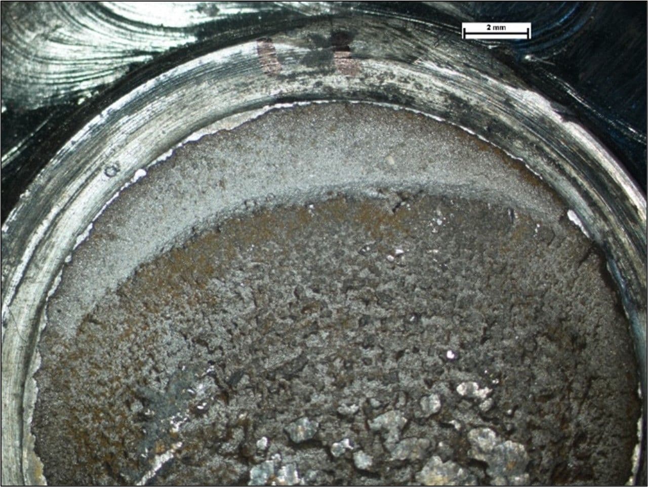
The image below shows the fatigue fracture of a circular beam used in the lifting mechanism of a crane. High cycle fatigue cracking had initiated on the top edge shown here, which coincided with a step at a reduction in its diameter. High cycle fatigue cracking propagated into the beam to a depth shown by the light-coloured crescent. The remaining fracture surface is darker and coarser, with indications of curved linear features extending across the fracture in the same form as the crescent, showing staged crack propagation by low cycle fatigue.

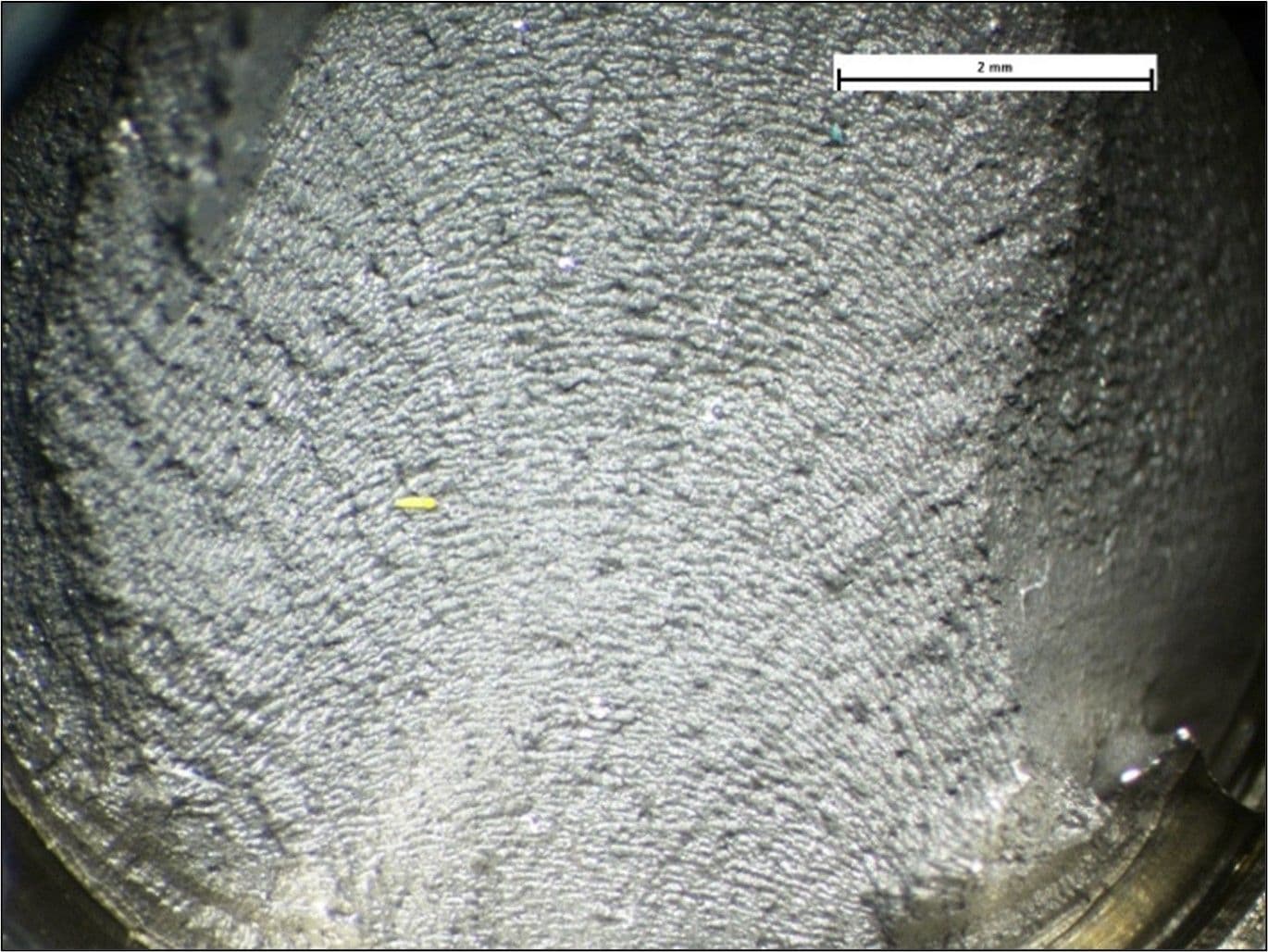
This next image shows the fracture face of a bolt used on the ‘big end’ of a connecting rod in a high-performance vehicle following laboratory-based endurance testing. The fracture surface is angled at approximately 45° to the longitudinal axis of the bolt and exhibits a series of regular curved features that progress across the surface. These features allow the origin of fracture to be identified, which was at the first thread on the bolt (just off the lower edge of the image). The regularity of these step features illustrated the constant cyclic loading on the bolt as may be expected from the endurance test conditions. Each step represents one stress cycle and with the engine operating at a high speed, the time to failure from crack initiation was short.

Avoidance
As with many failure mechanisms, a key factor in avoiding fatigue failures is in its awareness. However, failures caused purely by low cycle fatigue (rather than low cycle fatigue being generated in the final stages of failure initiated by high cycle fatigue) are not that common outside of the power generation industry and are often a result of some form of cyclic overloading. This may be a result of another problem that has developed within the ‘system’ rather than a result of poor design, manufacturing or material defects.
In the example of the bolt, described above, the failure was an isolated event and no evidence of manufacturing or material defects was found. Failure was then attributed to incorrect installation and likely associated with torque loading on the bolt pair on the big end of the connecting rod. Tightening procedures were reviewed and subsequently, no further failures occurred.
