Description
Creep is a time-dependant effect where stress below the yield stress of the material, applied at high temperature causes the material to stretch (plastic strain). This plastic deformation at high temperature is called creep. After a period of time, this continued deformation can lead to fracture, often called stress-rupture or creep-rupture.
Mechanism
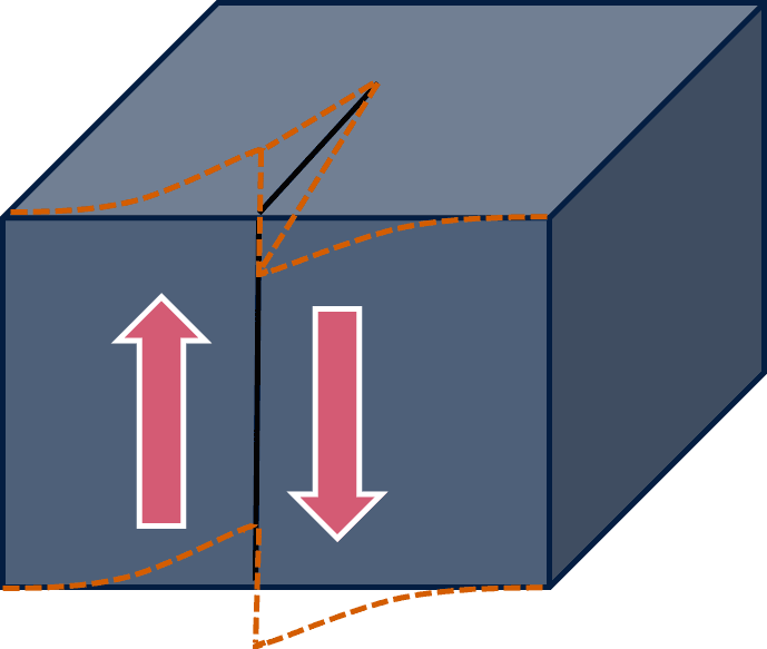
To understand creep mechanisms in more detail it is worth considering the metal at the atomic scale. A metal is made up of crystals with atoms following defined arrangements in the form of planes, but these planes exhibit faults such as gaps (vacancies), extra atoms ‘squeezed’ into the lattice (interstitials), or dislocations. Dislocations are imperfections in the otherwise perfect arrangement of the lattice and there are two types of dislocations: screw and edge. The screw dislocation may be visualised by considering a perfect stack of planes being cut part of the way through the crystal, and the cut edges then being moved, or sheared, by one atom spacing as in the diagram below.

New offset position of the crystal following shearing, shown by the yellow lines
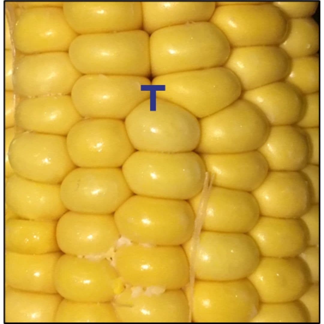
The edge dislocation can be visualised by the insertion of an extra plane of atoms part of the way into the crystal, such as a partially inserted card in a deck of cards, or that which is occasionally observed in a head of sweetcorn as it tapers toward the tip, as shown below!

The dislocation (T) is then the end of the extra row.
When the metal is subjected to a stress and hence strain, these dislocations can move and cause other dislocations to generate, resulting in small movements in the planes of atoms. High temperatures permit the dislocations to move with greater ease due to the increased (thermal) energy.
Looking further into creep, two mechanisms or forms may be considered: Diffusion creep and Dislocation creep. With Diffusion creep, the slow deformation of the material occurs by atoms or vacancies moving through the material’s crystal lattice structure by a climb process, from low stress regions to high stress regions which causes the grains to elongate in the direction of the applied stress. In climb, the dislocation moves in a direction generally in line with the plane of the extra row of atoms which has produced the dislocation. Using the deck of cards analogy, consider pulling out the card inserted into the pack by a small distance. Since this occurs on the scale of the individual grains, diffusion distances are shorter in fine-grained materials, which then tend to be more susceptible to creep.
Dislocation creep is a mechanism involving motion of dislocations. This mechanism of creep tends to dominate at high stresses and relatively low temperatures. Dislocations can move by gliding in a slip plane, a process requiring little thermal activation, in a manner akin to a ridge in a carpet being moved by the application of a small force to its side, ‘rolling’ it to its edge. It takes a lot less energy to move a carpet across the floor using this technique than trying to pull the whole carpet the same distance. This also applies to the movement of rows of atoms by gliding, compared to trying to get a whole plane of atoms to slide across another.
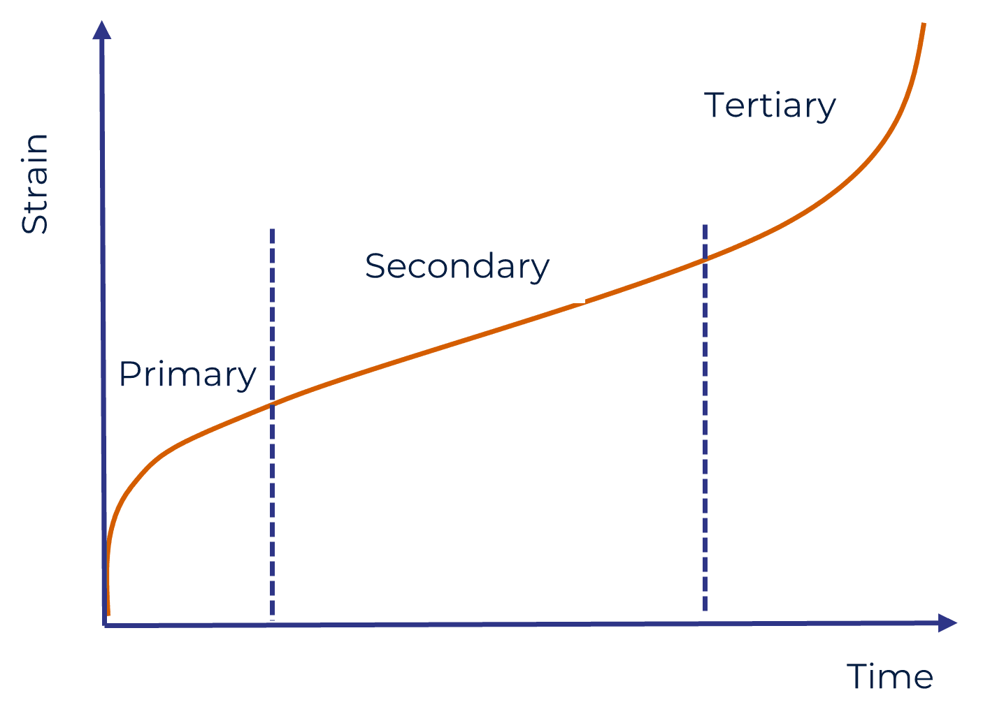
Creep in most materials can be considered as consisting of three stages, termed as Primary, Secondary, and Tertiary, as shown in the diagram below.

Primary Creep
The immediate effects of an applied load causes increasing plastic (permanent) strain, which reduces with time. This is effectively a stage of adjustment within the crystal or grain structure of the metal where the thermally activated plastic strain occurs within a short period of time after the initial loading. This adjustment is caused by the climb of dislocations away from obstacles such as precipitates, and slip, where the dislocations move perpendicular to the plane of the extra row of atoms.
Secondary Creep
Following the primary stage, the plastic strain rate reaches a constant rate of increase, and this is termed secondary creep; the rate at which dislocations climb away from the obstacles is matched by the rate at which the dislocations are blocked by other imperfections in the material.
When a metal is plastically strained it would usually work harden due to distortions to the atomic structure. This work hardening effect may be eliminated by heat treatment, but when considering creep, the material would already be operating in a high temperature environment and so the effects of work hardening are balanced by ‘recovery’ of the original structure; there is an equilibrium condition between the two effects.
Tertiary Creep
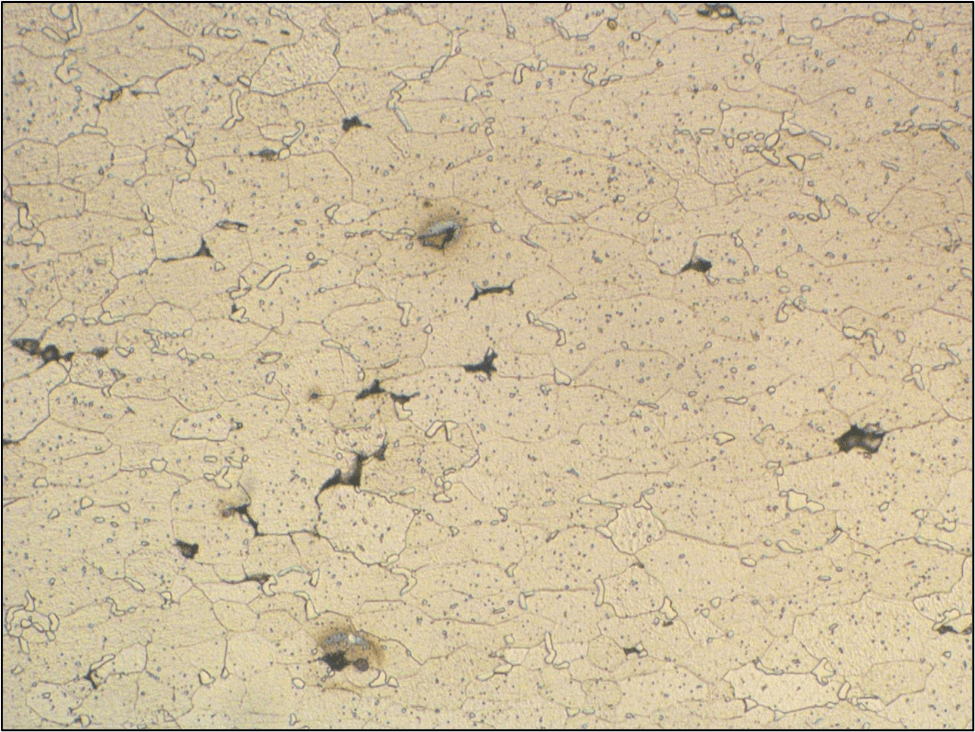
The last stage is where the strain rate rapidly increases with the development of voids at grain boundaries and then fracture. An image of the microstructure of a steel undergoing tertiary creep is shown below with the developing voids shown as the black areas.

The subject of creep has been researched extensively and various different mechanisms have been identified by researchers over the years, with each mechanism or mode often being named after its discoverer. For example:
- Nabarro–Herring creep considers bulk diffusion mechanisms, favoured at higher temperatures.
- Coble creep considers grain boundary diffusion, favoured at lower temperatures.
- Glide and climb-controlled dislocation creep, where dislocations move via glide and climb, and the speed of glide or climb respectively, is the dominant factor on strain rate,
- Harper-Dorn creep, is a low-stress creep mechanism which occurs in some pure materials,
Creep is also a phenomenon that occurs to ‘plastics’ i.e. thermoplastic polymers. Rather than organised structures of atoms that occur in a metal, polymers consist of chains of atoms and molecules bound with covalent bonds. These chains may be completely amorphous, or exhibit varying degrees of order, or crystallinity, and adjacent chains may also be bounded by weaker Van der Waals bonds and some mechanical interlocking.
The behaviour of polymers to loading, or stress, is dependent on the rate at which loading is applied and the subsequent strain rate. Thermoplastics exhibit a viscoelastic behaviour where on gradual loading, viscous flow occurs; the polymer chains slide past each other and the chains untangle and straighten out.
In an impact (high strain rate), the chains do not have the chance to slide and straighten out and the stress may be sufficient to cause instantaneous brittle fracture.
The melting point of thermoplastics is relatively low, such as 115°C for low density polyethylene, to 327°C for Teflon. Room temperatures may be sufficient to allow creep to generate at sufficient stress, but with increasing temperature, creep damage may develop.
Appearance
With metal components, creep may go unnoticed for significant periods of time until gross deformation develops, such as at the latter stages of secondary creep, and tertiary creep, although this is not generally obvious. The pipes used to transport high pressure steam in power generation plants may be prone of creep damage and regular inspections are carried out to check for creep damage. This is done by polishing small areas and examination of the microstructure to look for the development of creep voids as shown in the earlier image. High precision components may deform enough to bridge a small clearance, such as the elongation of turbine blades in an aeroengine, leading to contact of the blade tips with the surrounding shroud or body, although this again would be caused by the latter stages of secondary creep, and potentially tertiary creep.
Avoidance
The avoidance of creep is generally focused on having an awareness at the design stage. This will include an understanding of the operating conditions, clearly with temperature being prime, but also time at these temperatures, and the extent or duration of thermal cycles. Materials may be selected to provide the greatest resistance to creep damage, but which would also have to provide resistance to the effects of exposure to high temperatures such as with oxidation or high temperature corrosion. There is then, a balance to be struck between resistance to creep and resistance to other in-service environmental effects.
Materials may be modified, or ‘engineered’, to offer the best compromise, such as by modifications to grain sizes and structures, but also alloying to develop precipitates or other phases that may provide resistance to the movement of dislocations.
However, in situations where creep damage is a known risk, or problem, inspections are often employed to monitor creep damage, and to then identify components where damage has reached an unacceptable level, but clearly before catastrophic failure has occurred.
