Description
Fatigue is one of the most common causes of failure of engineering metal alloys. The cost of fatigue cracking to the engineering industry is vast due to failures, preventative measures, and replacement of components.
Fatigue occurs when a material is subjected to a fluctuating (cyclic) tensile stress and after a period of time, a small microcrack initiates and then grows progressively through the material until the crack reaches a point where the remaining section of material suddenly fractures. Sources of this cyclic stress may include vibrations in the system, stress cycling, and thermal cycling.
The first article on failure caused by cyclic stress was published in 1837 by Wilhelm Albert. His mine chains failed and so he made what was probably the first machine to simulate fatigue. He then went on to design the first braided steel rope. The term ‘fatigue’ began with Jean-Victor Poncelet, in 1839 when he described metals as getting ‘tired’. One of the first disasters reported as a consequence of fatigue was the Versailles train crash, which killed up to 200 people. It was Braithwaite that finally coined the word fatigue in 1854 when reporting on common service fatigue failures.
There are various forms of fatigue, such as rolling contact fatigue, thermal fatigue, creep and impact fatigue, and, as described in this white paper, corrosion fatigue. Corrosion fatigue may be described as the process of cracking by the simultaneous action of corrosion and cyclic loading, where cracking occurs at lower stress levels and fewer cycles than would be required in the absence of the corrosion environment.
Mechanism
Corrosion fatigue occurs when a metal component is subjected to cyclic stresses when in a corrosive environment, whereas fatigue occurs in the absence of this corrosive environment, and it could be considered a form of environmentally assisted cracking.
To understand fatigue, and corrosion fatigue, we need to consider the metal at the atomic scale. A metal is made up of crystals with atoms following defined arrangements in the form of planes, but these planes exhibit faults such as gaps. When the metal is subjected to a stress that is nominally below the yield point, i.e. in the elastic range, these defects, termed dislocations act as stress concentrations and will cause other dislocations to generate and some to move, resulting in small movements in the planes of atoms. Under some steady state loading conditions, this movement may ultimately reach a point where it stops and the material may be considered to have undergone ‘shakedown’; the material behaves truly elastic, and the material does not initiate cracking or generate further dislocations. However, if loading is sufficient but still below the yield point, plastic (permanent deformation) shakedown may continue and ultimately, at a free surface small extrusions and intrusions develop. With time these intrusions develop into small cracks. In the presence of corrosion, the process of crack initiation on an exposed surface, and then propagation is accelerated.
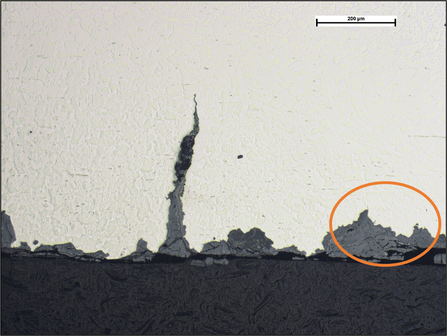
Some metals such as steel, exhibit a fatigue limit, which is a stress amplitude (fluctuating stress), below which fatigue will not occur, but the presence of corrosion eliminates this limit and the steel will eventually develop fatigue cracks. Metals such as aluminium and stainless steels do not exhibit fatigue limits and will then eventually initiate fatigue cracks when exposed to cyclic tensile stresses. Furthermore, corrosion can lead to small pits at the surface and these act as stress concentrations, driving cracking initiation, and pits are often observed at crack initiation sites as shown in the image below. This shows the surface of a steel shaft with a corrosion fatigue crack and pits, some of which have early stage fatigue cracks starting to propagate away from the base of the pit (circled).
Once initiated, cracks will grow a small amount for each individual damaging stress cycle and the crack advances progressively. The amount the crack advances on each of these cycles will be dependent on the stress level and to a degree, the corrosivity of the environment. Corrosion is constantly attacking the material at the crack tip, breaking down the surface at the crack tip, driving the crack forward. Crack tips are inherently sharp and are in themselves points of stress concentration. The material at the crack tip may experience a degree of work hardening due to plastic deformation and this may retard crack growth, but corrosion may continue to attack this material exposing the base material and allowing the fatigue crack to advance sooner. Conversely, high corrosion rates may cause rounding of the crack tip, reducing the stress concentration which may retard or stop crack growth. So, there is a balance between corrosion rate, stress intensity, and fatigue crack growth rate.
Appearance and Examples
Since fatigue and corrosion fatigue cracks are progressive in nature, subtle, or not so subtle variations in the appearance of the fracture surface may be observed. In many ‘real life’ applications, loading to cause fatigue cracking may be variable, with periods of unloading, high loading, or general changes in loading environment which will all alter the propagation rates which may be observed on the fracture face as steps, discolouration from contamination (oils and debris) or light corrosion, or changes in crack orientation. On a microscale, and particularly at very high magnifications such as that observed with a scanning electron microscope, small ripples on the fracture surface may be observed with each ripple corresponding to an individual loading event; these are termed as striations, compared to the larger features observed with the naked eye referred to above, that are termed as ‘beach marks’.
The beach marks may provide some qualitative information on the general crack propagation rates although it is not generally possible to age or date the crack unless specific service information is available to correlate beach-mark features with service history. For example, the fracture surface on the wheel that caused the derailment of a passenger train at Sandy, Bedfordshire, in 1998, exhibited an undulating ‘zig-zag’ topography with definite changes in the length of each fracture facet. Investigation of the relative sizes of these facet features showed a correlation with the journey history of the train which was well-documented; the zig-zag form corresponded to the train travelling north, and then south with the lengths of the facets relating to journey lengths. It was then possible to identify how big the crack was at any given date which was crucial in the subsequent court case.
Laboratory-based fatigue tests are often carried out in a controlled environment (i.e. in the absence of corrosion or contamination) and with constant stress amplitudes. Fracture faces may then be relatively devoid of features from which to assess crack growth rates. In-situ non-destructive tests may be carried out to monitor crack growth rates. Alternatively, the stress amplitude may be deliberately changed at set periods to generate small step features on the fracture face. This then enables the progression history of the crack to be investigated on completion of the test, and the fracture face is studied. However, the fracture faces of corrosion fatigue cracks will often be attacked to varying degrees by corrosion. As cracking progresses, the early stages of the crack may be completely or partially destroyed causing the crack to widen at the surface and it is then rarely possible to determine crack growth rates by examination of the fracture surface, and striations will typically be destroyed.
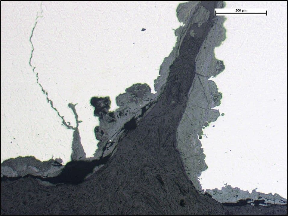
During microscopic examination of sections cut through cracks, corrosion fatigue will often be identified by corrosion attack/deposits, and occasionally minor side-branching of the cracks as shown below.
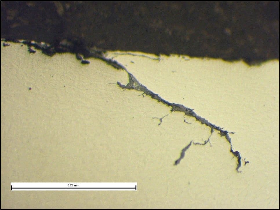
This was caused by heavy fretting on the shaft of a water pump. Fretting had caused plastic deformation and wear of the shaft surface and combined with corrosion, had initiated fatigue cracks, which is not uncommon on fretted surfaces. Due to the cyclic stress from operation of the pump, and the corrosive environment, corrosion fatigue cracks had propagated through the shaft leading to its complete fracture.
The image below shows the heavy corrosion fatigue attack of the underside of a track plate used for an amusement park ride.
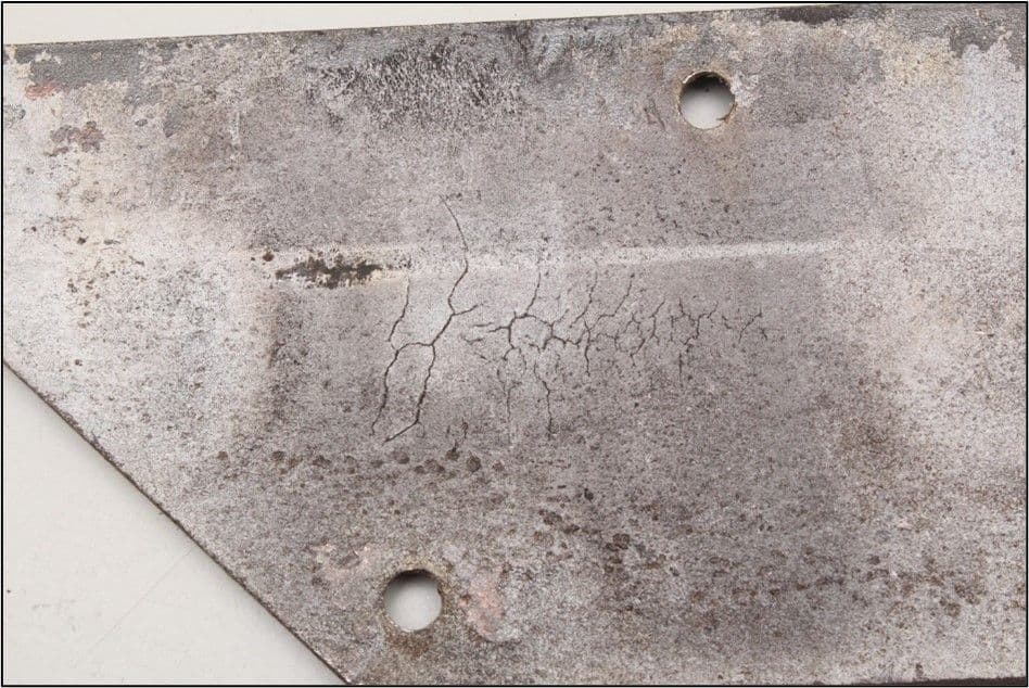
Due to the design of the track, the track support allowed for its flexure, inputting a cyclic stress from bending, with the underside of the track plate in tension. In addition, the underside of the track plate remained wet for prolonged periods of time, through contact with the main structure of the ride, creating a crevice and driving corrosion. The two images below show the severity of the corrosion attack on the underside, widening of the cracks at the surface, secondary cracks, and corrosion pits.
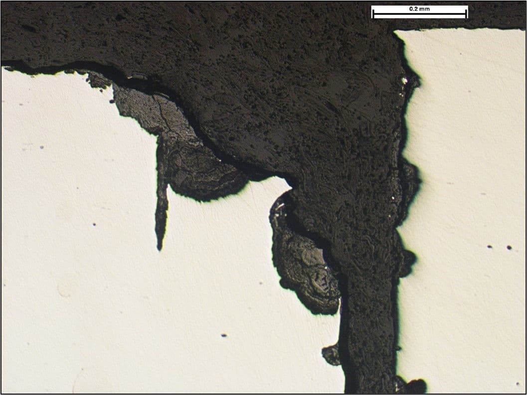
The cracks were only discovered during routine non-destructive testing (NDT) using magnetic particle inspection (MPI) of the running face of the track plate which identified a network of cracks on the surface, which had propagated through the full thickness of the plates. The extent of the cracking was severe, but isolated, with the body of the track plate which, at the point of inspection, had sufficient structural integrity to have remained serviceable. However, the condition of the track plates was clearly poor and failure by complete fracture could be considered to be ‘imminent’, with the implications of this on an amusement park ride.
Another example is the failure of a carbon steel shaft that was used in a pump application. The image below shows the fracture and general condition of the shaft, being heavily corroded.
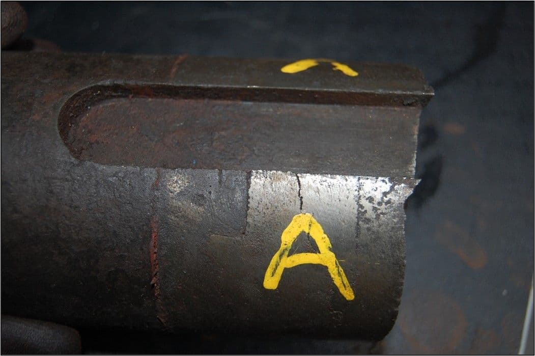
The fracture face exhibited features indicative of fatigue and when microscopic examination of sections through the surface of the shaft was carried out, additional branched cracks were observed as shown below.
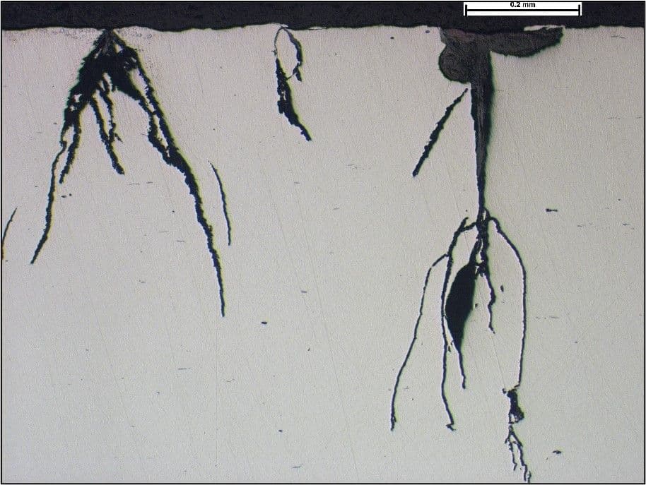
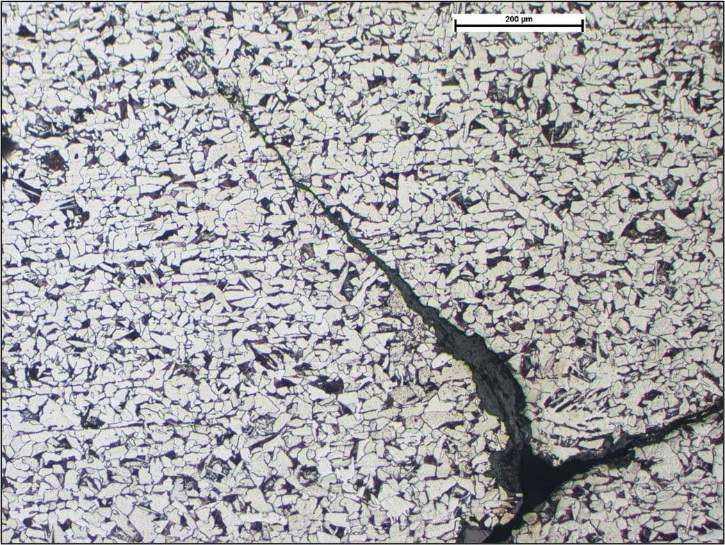
In the etched condition, the cracks were observed to have propagated in a transgranular manner, as expected, through the microstructure that consisted of grains of pearlite in a ferrite matrix shown below.
Avoidance
As discussed above, corrosion fatigue cracks initiate much sooner than would the same component exposed to the same stress cycles in the absence of corrosion. One of the main factors to consider in avoiding corrosion fatigue is then the elimination of corrosion. This could be by changes in the environment, but more often than not, the environment is fixed and isolating the material from the environment is necessary, although in controlled environments, the use of chemical inhibitors may be possible.
Isolation of the material from the environment may be achieved with the use of coatings but the integrity of the coating would be critical. Breaches in the coating could cause relatively severe, localised attack at those sites of damage, from concentration of the damaging species, leading to crevice or pitting corrosion.
Reduction of the stress amplitude in the component could be achieved by changes in the design of the component or of the system, to reduce for example, stress concentrations and vibrations respectively.
If sufficient changes cannot be made to reduce the probability for corrosion fatigue cracking, regular NDT may be a solution to monitor the condition. In the example of the track plate used in the amusement park ride, the routine NDT clearly identified the cracks before a catastrophic failure occurred, although in this example, the cracks were well advanced to a point where complete fracture could have occurred in a relatively short but unpredictable time. In this case, the inspection periodicity should be significantly reduced.
