Description
These two terms may occasionally be (incorrectly) used interchangeably but they are different mechanisms. Yielding is the failure of a component due to an applied stress that is greater than the material’s yield stress, hence ‘yielding’, and which does not necessarily cause fracture. With yielding, the material plastically deforms (i.e. permanent deformation rather than elastic deformation where the component would return to its original dimensions on release of the stress). Buckling however, is the sudden change in shape of a structure under load, is a function of the geometry of the component, and is often associated with thin-walled cylinders, struts, and columns.
Mechanism
Within the field of structures, as referenced above, buckling may be considered as the sudden or rapid change in shape of a component under a load. Once buckling has initiated, the resulting deformation causes the material to yield. ‘Failures’ of materials are usually associated with their strength, an inherent property of the material, but buckling is a combination of its shape or geometry and the material’s elastic modulus. Fracture or cracking of the material may not necessarily occur, although this depends on the level of ductility in the material, which is related to the elastic modulus. Typically, a structure buckles by plastic deformation and yielding of the material, but in the latter stages of collapse, deformation may be so extensive that the material eventually fractures.
A common example of buckling involves long and thin structures such as columns or struts. For a particular compressive load, the properties of the material(s) used in the construction of a column may be expected to be able to support the load, but the column can still collapse, by buckling. In 1757, the mathematician Leonard Euler, derived a formula that demonstrated this behaviour of columns under axial loading.
Where;
F, is the maximum (critical force)
E, is the elastic modulus of the material
I, is the area moment of inertia of the cross-section of the column, and sometimes termed the second moment of area
L, is the unsupported length of the column, and
K, is the effective length factor e.g. with fixed ends K=0.5, but if the ends are pinned and free to rotate K=1.
Buckling however, not only applies to columns, but to any structure that, under compressive loading, suddenly moves to another shape. For example, plates or cylinders may be considered to comprise a series of infinitesimally thin columns and can behave in the same manner.
At the point of buckling, with the force (F) at its critical or maximum level, the column or structure is said to be in a state of unstable equilibrium. In this state, the slightest increase in loading or sideward deflection will cause the instantaneous collapse. There are many video clips available online to show this effect, where a cylinder at the critical force is lightly tapped, inducing instantaneous collapse. It should be noted that, even though the component is under compression, it is not the compressive strength that is a governing factor, but the material’s elasticity, hence the significance of the modulus of elasticity term in the Euler equation. In addition, increases in length result in a rapid reduction in the buckling load, given that the length variable is squared i.e. if the length is doubled, the buckling (critical) force is quartered.
Appearance and Examples
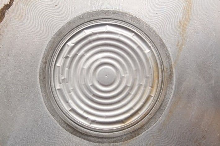
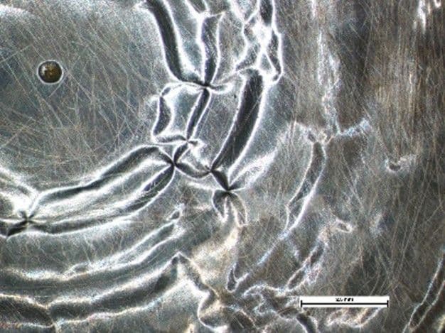
Buckling is usually manifest by distortion and collapse of the structure, and typically as plastic or ductile yielding. Large thin-walled cylindrical vessels subjected to compressive loading through the axis will often buckle and collapse in a regular pattern of creases. A search on the internet will generate many images of columns, beams, and cylindrical structures that have buckled or yielded, but buckling is not just associated with such structural forms. It can also occur on other structures too. An unusual example is that of a circular ribbed diaphragm plate that was exposed to an overpressure event. This resulted in collapse of the structure, causing a regular pattern of radial folds, as shown in the images below. As an aside, the diaphragm continued to operate adequately for a short period of time before the material at the folds was breached by small cracks, at which point the component malfunctioned due to release of the process fluid. Investigation found the cracks to have been caused by a stress corrosion cracking (SCC) mechanism (see our other white paper on SCC). The environment was mildly corrosive, but the material was normally able to resist any corrosion attack i.e. when in a stress-free or low stress state. However, the generation of the folds caused localised increase in residual stress in the material which was then sufficient to generate SCC.


Another example is that of a large cylindrical tank used in the processing of liquid. This was subjected to a caustic clean at 80°C and then rinsed through with cold mains water. Shortly after, the tank collapsed in on itself, by buckling. The introduction of the cold water had rapidly cooled the vessel.
This reduction in temperature would cause the volume of air to reduce (contract), which should not have been a problem were it not for a malfunctioning pressure relief valve (designed to allow the pressure in the vessel to equalise with the external (atmospheric) pressure). The reduction in internal pressure eventually reached a point where the pressure difference was sufficient for the atmospheric pressure to ‘crush’ the vessel.
Railway tracks are usually constructed from sections of rail, welded together to form long lengths (CWR – continuously welded rail) with ¼ mile lengths or more not being unusual, effectively acting as long columns. With variation in temperature as the weather changes, the sections of rail expand and contract, and for a nominal temperature increase of 55°C, a ¼ mile could lengthen by approximately 250mm. If the rail was prevented from movement at each end, this increase in length would generate compressive loads, and if it was poorly fixed along its length, the rail could suddenly buckle, usually by a lateral (sideward) deflection. This effect is mitigated by applying a tensile stress to the rail whilst it is laid and then clipped to each sleeper or track support. The tensile stress is selected to optimise the balance between prevention of buckling at high temperatures, whilst keeping tensile stresses within a reasonable level to reduce the risk of fracture at low temperatures. There will clearly be a temperature at which the installed tensile stress is reduced to zero from expansion, and this is termed the stress-free temperature (SFT). For rail in the UK, this is in the order of 21-27°C depending on the conditions at the time of installation. Temperatures above the SFT then generate compressive stress in the rails with an increasing risk of buckling with temperature.
Avoidance
A key factor in the prevention or avoidance of buckling is in the understanding of the loading, and then ensuring the design of any structure does not increase the likelihood of reaching the point of failure, or buckling instability. If there is a concern that buckling could occur, or that the consequences of failure were significant (although perhaps unlikely), then additional measures could be employed to further strengthen a structure, such as the use of braces or other similar cross-members. However, initial considerations for prevention of buckling should be focussed on the design, and the parameters in the Euler equation. For example, materials could be selected that offer increased stiffness/elastic modulus, sectional forms that exhibit an increased second moment of area, but also a reduction in the length, and effective length, of the column.
In the case of the diaphragm plate, there would be little advantage in changes to the design or of the materials. The overpressure event was caused by a defective valve in the system that was unforeseen, and the subsequent SCC was again unforeseen, and perhaps reasonably so as this was only caused by the formation of the folds from overpressure that generated residual stress.
The collapse of the cylindrical tank was caused by a faulty pressure relief valve. The operation of these should be routinely checked and particularly in this application where sudden temperature, and hence volume/pressure changes are known to occur. This then, was caused by inadequate maintenance procedures.
As for the railway, the public may complain about such effects as ‘leaves on the line’ (an entirely different subject!) or high temperatures causing trains to run slower, but there are real dangers associated with these problems, that engineers and scientists continue to work on to resolve or provide some form of mitigation; nobody wants to be on a train when the rail beneath it suddenly buckles!
